I assume you’ve seen or read Harry Potter. If so, you might remember the Weasley clock pictured here. Each hand represents a member of the Weasley family, and would move around in order to indicate where that family member was currently.
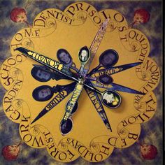
As you may or may not know, members of my family currently live in three different countries (with one of them hopping from continent to continent, but that’s another story), so I thought it would be cool to have a way to know, at a glance, where everyone was .
In order to limit overprotective behaviour, I decided that this would be a physical object, bound to a specific location, instead of an app. I would keep the same number of locations, twelve, but would use LEDs instead of clock hands.

Here’s a preview of the architecture I’m using
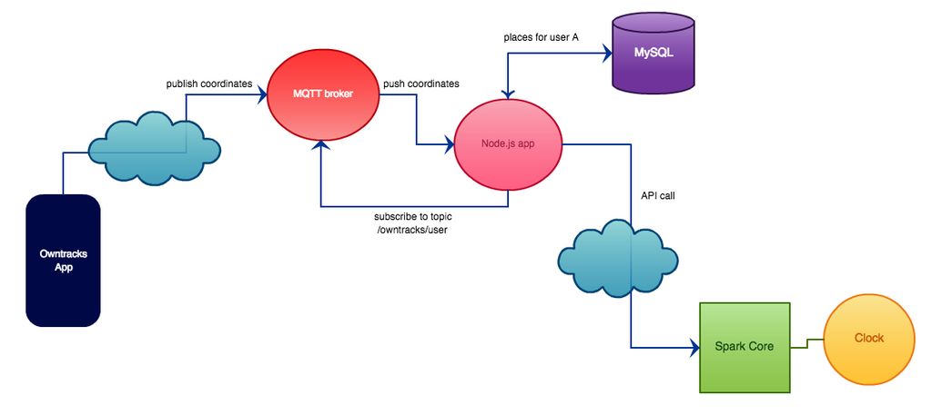
Each member of the family has a smartphone : let’s take user A, who has an Android phone.
On this phone there’s an app that follows their current location (the app works on iOS as well). When the app detects user A has changed location, it sends the current position (geographic coordinates) to a server. The protocol used is MQTT, so the server is called the “broker” and the app on the smartphone “publishes” to it.A node.js application running on a server has “subscribed” to every update for user A, so it is informed of this new position. The server knows the geographic coordinates for every possible place for user A : at home, at work, etc. It compares the current position to this data and concludes the user’s location. It then makes an API call on the Spark cloud for the clock to change accordingly.
How does the server know the coordinates for every possible place for this user ? It fetches them from a MySQL database every six hours, so if a user changes their favourite restaurant or their workplace, the code still works, they just have to update the coordinates in the database.
I first thought I’d be able to make the clock using regular LEDs and a few shift registers, so I made a custom PCB in order to go from this …

… to this …

The end result was still to bulky and complicated to wire so I switched to neopixels instead.
From that..

.. to this !

Of course this made things much easier. The disks on which the LEDs are glued are laser cut from MDF, and a bigger disk underneath it hosts the rest of the electronics, namely the Wifi-connected Spark Core that drives the NeoPixels and the white LEDs under each symbol of the clock.


I then added some PMMA “rings” stacked together in order to build an enclosure for the clock.

Finally, I also added a ring of MDF with the icons for each location laser cut, so that the white LEDs would shine through.

I was thrilled to have my project selected for the 2015 Maker Faire !


If you want to read more about this project, I have made a instructable which includes the code and PCB stencils I used : http://www.instructables.com/id/Weasley-Clock